DIY Projects |
||
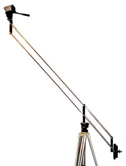
Camera Crane
This is my Camera Crane. Also known as a Jib Arm. If you wish to build your own. Some welding will be required.
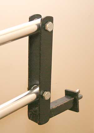
For the jib arm I used two aluminium tubes 180 cm long. The distance from the camera support to the fulcrum is 130 cm and from the fulcrum to the weight hanger 50cm. Originally I built the jib arms from square steel when I had heavy on the shoulder cameras. When these were replaced with the modern lightweight cameras I replaced the steel tube with aluminium tube. I used round tube but square tube is easier to work with. It is easier to drill the holes squarely and in line. The square tube also holds the assembly square so there is less need for accuracy in drilling. I will be replacing the round tube with square aluminium tube to make it more stable. I made three steel yokes that are basically the same. Just two pieces of strap steel with a piece of square tube at one end cut to match the diameter of the jib arms, plus enough space for two washers. One washer goes each side of the jib arm tube inside the yoke. The holes are drilled to match the size M8 bolts and the bolts are secured with Nylock nuts.
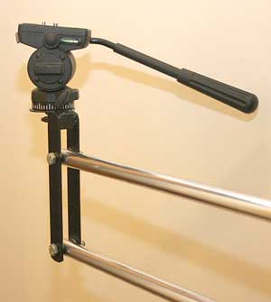
The camera support has the piece of square tube at the top. Welded to this is a large flat washer to support the camera. You will need a quarter inch whitworth thumb screw to hold the pan head. You can get the ideal one from a camera shop. Ask for a case screw or a flash bracket screw.
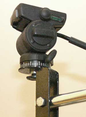
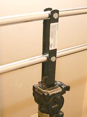
The Fulcrum yoke is longer and has the piece of square tube at the bottom. This has to be longer so it doesn’t foul the lower jib arm. Welded to the bottom is a flat plate with a quarter whitworth threaded hole to take the tripod screw. I used an old pan head with the tilt locked and the handle removed. I attached the whole assembly to a sturdy tripod.
The yoke for the counterweight end has the piece of square tube at the bottom. Welded to this is another tube long enough to take the weights. I used weight lifting weights which you can buy from a sporting goods shop. Having the support tube attached to the yoke keeps it level so the weights don’t fall off. However you should always make sure the weights are secure. This is why there is a bolt welded onto the end of the weight hanger with a big washer and a wingnut.
This crane is designed for a very light camera. Make sure your jib arm tubes are strong enough to hold your camera. If the overhang at the weight end is made longer you can use less weights to get a balance. Coming soon. How to make a yoke to hold the camera below the crane. Good for close to the floor shots.
©2009 Ron H Bannister Auckland
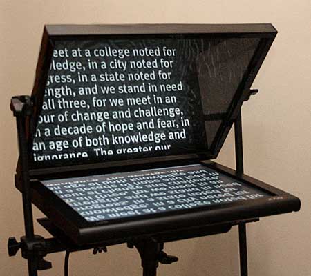
This is my Prompter. Also known as AutoCue and TelePrompter but these are brand names so I will just call it Prompter. Click here for construction details and how prompters work.
www.videomakers.org.nz/auck.htm Auckland's Video Camera Club
Viewfinder Magazine
New Zealand's own Video Magazine |
Camera Dolly
This is my Camera Dolly. This is a simple dolly that has no steering or crabbing so can only travel in straight lines with the pnumatic tyres. Since it is lightweight and doesn't have all the features of a studio dolly. one like this is usually called a location dolly or a doorway dolly. I decided against complications of steering, as most dolly shots are in straight lines going to or from things and travelling alongside people walking. This project also requires some welding.
This is the plan for the frame of the dolly. The dolly is designed to be compact and easy to transport in the back of my station wagon. The frame is in two pieces, that is two frames each being about 450mm square. At the location they are fitted together to make a platform about 450 mm by 900 mm. Then the axles are slid into the axle tubes and the wheels clipped on. The frames are made from 20mm x 35mm rectangular steel tubing. Welded to the frames are 20mm tubes to take the axles. The dolly is designed to fit through a doorway. It has pneumatic tyres but these can be replaced by bogies with skateboard wheels to use as a track dolly. The bogies will ride on PVC water pipe tracks. When used as a track dolly the bogies will follow curved tracks.
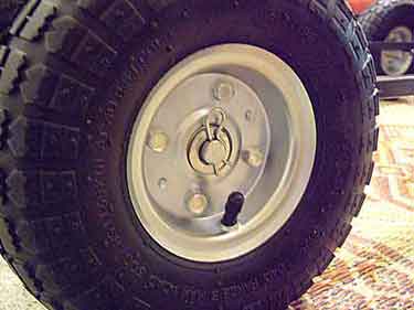
This is how the wheels are attached with "R" clips. No tools needed. The bogies will also be attached with "R" clips.
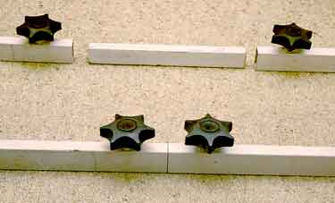
These are the side tubes of the frames. This picture shows how the two frames will be joined together. A short smaller tube fits inside the larger ones. Two big hand screws are tightened up to hold it all together. When the dolly is completed the hand screws will be on the underside. The side tubes are drilled with holes big enough for the screws to pass through. Then nuts are welded over the holes to take the hand screws. M8 screws are a good size.
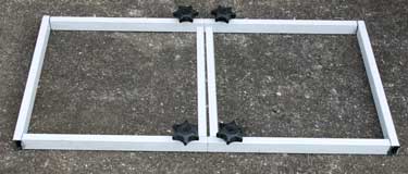
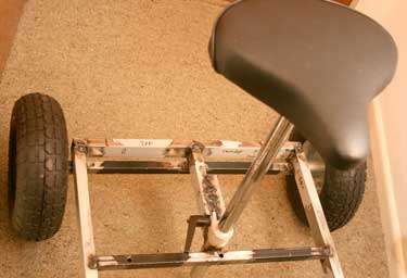
As you can see the frame is starting to take shape.
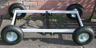
Here it is with the wheels.
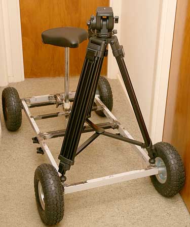
Now the seat is installed. It is from an old Exercycle. The seat post can be removed and is clamped into the frame. Another source of a seat could be a drum stool from a music shop.
The Dolly can be used in skeleton form like this but the floor panels make it look better and there are more places to put your feet.
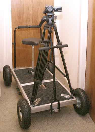
Here is the completed Dolly.
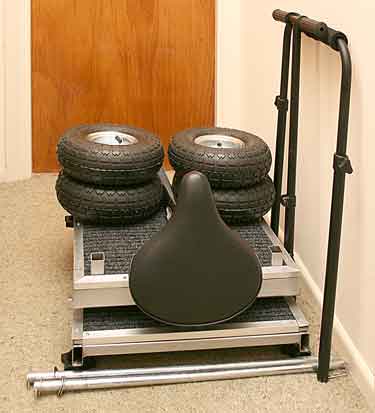
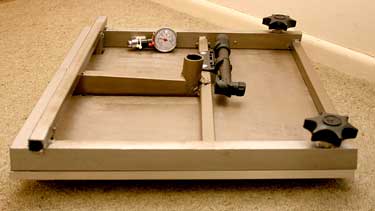
This is how the dolly breaks down for storage or transportation.
This is the underside of the platform half with the seat. This is where the tyre pump and tyre gauge are stored.
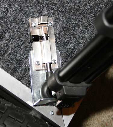
Detail of tripod mounting. I used a metal bracket and a bolt with a rubber "chair tip" on the end. This is custom made for my tripod. Instead of the bolt, you could use another bracket with a thumb screw, then it would adjust to fit different tripod feet. I used the bolts for speed.
©2009 Ron H Bannister Auckland |
|


|